2D, 2.5D and 3D Precision Laser Manufacturing
A Polaris UniverseOne™ motion control system has been designed for precision laser manufacturing. From applications such as 2D, 2.5D and 3D laser micro-machining and precision deep engraving, to multiple scan head 3D metal printing applications, a Polaris UniverseOne system has the tools and technologies needed to create the best-in-class laser CNC machine tool.
A part is designed using a CAD program such as AutoCad, Fusion 360, Inventor, SolidWorks, CATIA and others. Designs can be 2D, 2.5D and true 3D, and the output file that describes the part can be a DXF file (2D), STL file (2.5D), or STEP file (3D). These are the most popular file formats, but there are others.
There are many precision laser manufacturing processes that have been considered, which are categorized as additive, subtractive, joining, and material transformation. In the additive category there is SLA, SLS and SLM. In the subtractive category we have cutting, drilling, engraving, etching, and ablation. Welding is a joining process. Some material transformation processes include impedance modification and annealing of metals.
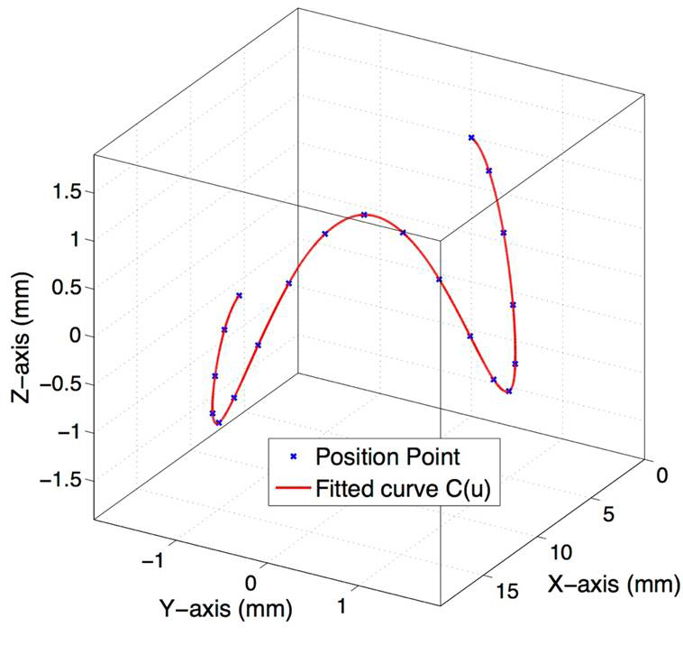
The Trajectory Generator
The CAM software exports Cartesian line, arc and spline primitives to the Polaris UniverseOne™ controller. Using a high level of intelligence, the Polaris setpoint generator evaluates the speed and acceleration capabilities of the mechanical stage axes and the laser optic Galvo scanner axes. With this evaluation, the Polaris UniverseOne™ controller runs the part program as fast as the machine can go. If an operator commands the machine to go faster than it is able, the software slows down the execution rate and the job runs to completion in the least amount of time possible.
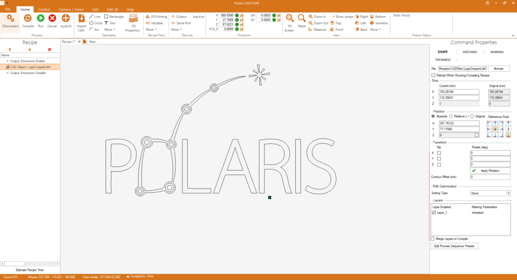
Polaris CAD/CAM
Polaris CAD/CAM (PCC) is software which is used to control laser CNC machines. All of the above-mentioned laser material processing operations can benefit from using PCC.
For 2D processes the DXF file is imported into PCC and attributes are set in preparation for cutting, drilling and hatching. The software automatically generates the tool path according to optimized path planning. When the operator hits RUN, a G-code file is generated and sent immediately to the Polaris UniverseOne™ motion controller for execution.
In the case of additive manufacturing, the three-dimensional STL file is imported and attributes are defined for contouring, filling and creating supports. PCC slices the STL file, potentially into thousands of layers. One or many scan heads can be used. If multiple scan heads are used, the part is separated in tiles, tool paths are created and a G-code file is created for each Galvo scanner. Advanced methods are employed to stich the overlapping areas together.
For true 3D subtractive applications, such as deep metal engraving on a 3D part such as a sphere, the 3D STEP file is imported into PCC and a 2.5D pattern is wrapped onto the sphere. A toolpath is automatically generated which can be executed on a 5-Axis CNC machine.
For high productivity, the combination of a 5-Axis CNC stage together with a 3D Galvoscanner can be used. The tool path is created, and the G-code file is sent to the Polaris UniverseOne™ motion controller. Polaris Motion’s unique 5-axis infinite field of view (IFOV) algorithm runs and the toolpath is automatically separated into stage and scanner motion.
>>Learn More
Cartesian G-Code
With a Polaris UniverseOne™ motion controller, productivity increases by using Cartesian G-code. The tool path is defined for the tool tip position, in the workpiece coordinate system. The machine geometry is decoupled by using inverse kinematics. This new approach makes computer aided manufacturing (CAM) easier because CAM doesn’t need to worry about machine geometry.
>>Learn More
Robotics and Machine Geometry
The machine geometry that maps the tool position and orientation to motor movements is encapsulated in the world file together with the machine’s kinematic constraints. Polaris has developed a library of machine geometries for common machine types. By implementing machine geometries using robotics tools, and by expressing Cartesian tool path motion in the part file coordinate system, it’s easy for 5-Axis CAM programs to generate laser tool paths.
>>Learn More
Laser Control Interface (LCI) Technology
Polaris UniverseOne™ servo motor drives, stepper motor modules, and Galvo control modules are equipped standard with a laser control interface (LCI). Due to Polaris Motion’s patented Gbps motion control network, nanosecond synchronization is achieved across all modules and any module with a LCI connection can be used to control a laser.
The LCI can control pulsed lasers and continuous wave (CW) lasers. In pulsed mode, fixed pitch triggering and pulse on demand (POD) triggering can be employed. Pulse rates in the MHz are possible. For CW lasers, PWM control can be used to regulate power with speed, and analog laser pulse shaping (ALPS™) is available to fine tune sensitive processes such as laser welding.
>>Learn More