Machine Control & CAD/CAM Software for Laser CNC Machines
Polaris CAD/CAM (PCC) is Polaris Motion’s computer aided design (CAD) and computer aided manufacturing (CAM) software. It is used in motion control design to control your laser source, positioning stage, Galvo scanner, machine vision and other laser CNC machine tool peripherals.
Polaris CAD/CAM is a powerful operating interface that increases productivity for a large number of laser manufacturing processes such as laser cutting, engraving, and welding, laser micromachining, laser ablation and 3D printing.
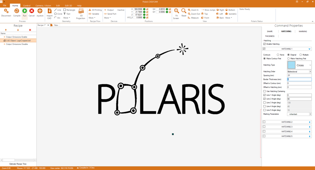
CAD Import & Part Preparation
The first step is to import a CAD file. Our motion control design software supports many different formats, including DXF, DWG, STL, NC Drill files, and bitmaps. During CAD import, all objects are preserved as lines and arcs. After import, the object is dragged in to place, and scaled if necessary. The integrated drawing tool may be used to add text, geometry and perform edits.
The next step is to choose and add hatching to closed areas. Many hatching pattens are available and they can be selected from a pallet.
The final step is to select the working speed and to press RUN. Polaris CAD/CAM automatically creates the tool path according to advanced algorithms for fast and accurate tool path execution.
Stage & Galvo scanner Coordination
When a Galvo scanner field of view is too small for the part that needs to be made, the Galvo scanner can be mounted onto an XYZ stage and be moved from one tile to another to cover the entire workpiece. This technique is called step and scan. “Stitching errors” can often occur in step and scan processes, especially at the extremities of the Galvo scanner field, where optical aberrations are greatest.
Infinite field of view (IFOV) is the recommended process when better precision is required. In an IFOV process, the stage and the Galvo scanner move simultaneously, and due to the continuous nature of the motion and the advanced algorithms involved, stitching errors are no longer an issue.
Machine Vision & Alignment
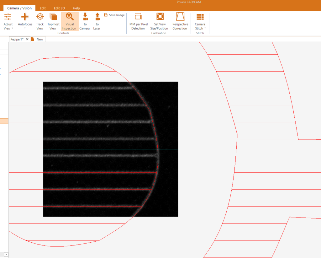
Polaris CAD/CAM offers advanced machine vision (MV) capability in its motion control software. Its main uses are (1) part alignment, (2) stage and Galvo scanner calibration, and (3) part inspection. Several machine vision cameras are supported. One camera can have a large field of view for general inspection. Another camera can be used to view small features. Both on-axis and off-axis views are supported.
The machine vision camera view can be super-imposed onto the CAD drawing for workpiece inspection. Alignment can be automatic or manual. Up to four fiducial marks can be used to find the orientation of the part. After alignment the recipe is rotated to match the camera view.
Automation & Recipes
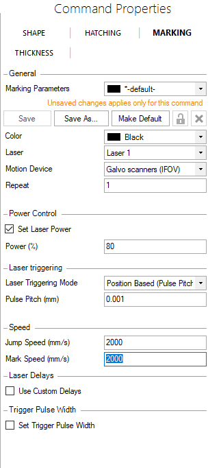
Polaris motion control design package CAD/CAM uses recipes and automation to create complex parts. Within the recipe, variables and program flow control are used for repetitive tasks. Laser power and scanning speeds can be changed for different sections of the part file by using variables. A machine vision camera can be used to create a height map and the laser focus can be adjusted automatically in the loop using variables. External triggers originating from digital I/O hardware can be used stop or start a process.
Remote Control Module (RCM)
Polaris CAD/CAM has a remote-control module option. Client software can control PCC via TCP/IP and PCC can run head-less. If you’re an OEM customer, you’re able to develop an operator interface using your own branding.

Give us a call or ask a question! Me and our team are always happy to help!
Tom Erlic, Business Development
5-Axis CNC Machine Tool Motion Control
PCC has the ability to make true 3D laser processed parts. A 5-Axis stage comprising of XYZ linear axes and AC rotational axes, together with a 3D Galvo scanner can be controlled.
A 2D or 2.5D pattern is wrapped onto a 3D part and laser process parameters are set. Polaris CAD/CAM along with the Polaris UniverseOne™ motion control system implements the trajectory generation and process control to fabricate the part.
Multiple Galvoscanner Control
In some applications manufacturing throughput is process constrained. This is often the case in selective laser melting (SLM) which is used for 3D metal printing. When throughput is an important requirement, there’s a need for multiple lasers. To accommodate this case, PCC has the ability to control multiple laser Galvoscanners simultaneously.
Additive Manufacturing
PCC has been designed for quick and effective laser additive manufacturing (AM) and 3D printing for processes including stereolithography (SLA), selective metal sintering (SLS) and selective laser melting (SLM).
In preparing a job, multiple different STL files can be imported into PCC or one STL file may be duplicated many times. Then the 3D printing command can combine all the parts into a single job run.
By optimizing computer resources, large STL files having hundreds of megabytes and millions of triangles may be sliced in seconds rather than minutes and hours. The resulting toolpath consisting of lines and arcs is sent to the Polaris UniverseOne™ motion controller automatically for immediate job execution.
STL files can be conditioned manually and/or automatically. Missing and extra planes are repaired and gaps are filled. Potential errors are flagged for repair. A variety of hatching patterns including line, cross-hatch and contour may be chosen to fill and prepare the volumes. Supports are automatically generated based on the part geometry, and they are created with easy removal as an objective.
For larger parts and for parts that need to be made quickly, multiple Galvo scanners can be used simultaneously. The job is split into tiles and methods are used to stitch the sections together with accuracy.