New Laser Control Techniques for 3D Metal Printing, Welding, Engraving and Micromachining
Laser control is required for many manufacturing processes such as cutting, drilling, welding, etching, engraving and ablation. Fine laser control is needed for powder bed fusion (PBF) and for directed metal deposition (DMD). Lasers are used for material altering processes such as annealing and quenching for metals, and modifying impedance in semiconductors.
For each of these processes, there is a preferred technique for controlling the delivery of laser energy. The two broad classes of lasers are continuous wave (CW) and pulsed. CW lasers are typically lower cost and have the advantage of high average power. Pulsed lasers have lower average power, but the short pulse photon energy breaks the material’s chemical bonds instead of burning. The heat affected zone (HAZ) is minimized, cuts are clean and material post processing is often unnecessary. In Polaris Motion’s laser control suite, both CW and pulsed lasers are supported.
Continuous Wave (CW) Lasers
A CW laser is a laser that emits a continuous laser beam with controlled heat output. For CW lasers Polaris Motion provides both pulse width modulated (PWM) control, and analog control. With PWM duty cycle control, the percentage of time that the PWM signal is high controls the intensity of the laser. As an example, if max power is 200W corresponding to 100% duty cycle, then a duty cycle of 25% results in 50W of continuous laser power. Duty cycle can be changed instantly.

Many lasers have an analog control input. These are typically 0-10V or ±10V, and can take any value in that range. For these, the laser power output is directly proportional to the control signal input. In the 0-10V case, if the max input signal of 10V corresponds to 200Watts of laser power, then 3V would result in 60Watts. The analog input Voltage can be changed instantly, resulting in instant changes in the laser output power.

PWM Control for CW Lasers
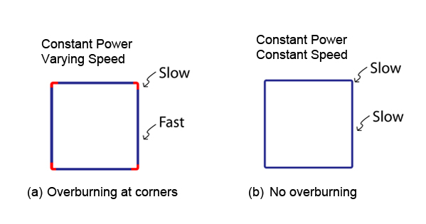
Constant power CW lasers have been popular for a long time due to their wide availability and low cost. However, to avoid hot spots and over-burning laser processing must occur at a constant speed to match the constant output power of the laser. By doing this, a constant amount of laser energy is deposited per unit length along the processing path, see Fig. 3b. The problem with constant power lasers is that maximum processing speed is limited by the cornering speed. The cornering speed, which is limited by the machine’s ability to accelerate and decelerate, becomes the maximum over-all speed of the process. If an operator tries to go fast along the straightaways and slow around the corners to maximize part per hour throughput, overburning at the corners will unfortunately result.
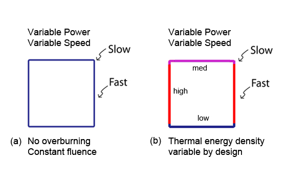
Fortunately, at Polaris Motion we offer the ability to change laser power automatically using duty cycle PWM control. Laser power can be changed instantly to match the laser processing speed along the work path resulting in even deposition of laser energy (fluence) as shown in Fig. 4a. Furthermore, if it’s necessary to have variable laser energy deposition for a special process then the ratio of laser power to speed can be changed automatically, as indicated in Fig. 4b.
Analog Control for CW Lasers
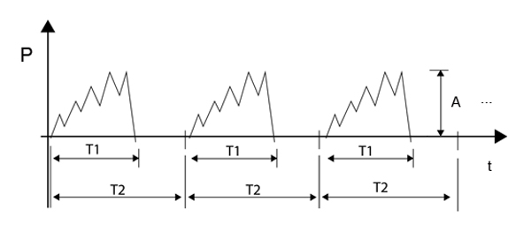
Analog control of CW lasers is also supported. The simple method is proportional control. The laser output power is simply proportional to the control signal input, which can be made proportional to the speed along the path as one example. However, Polaris Motion also offers Analog Laser Pulse Shaping (ALPS™), see (Fig. 5). The operator has a number of control levers, including: the pulse shape itself which is created in a table, the amplitude (A), the on time of the pulse (T1), and the pulse period (T2). ALPS™ is useful for controlling the thermal energy density of a melt pool for both laser welding and for metal 3D printing applications.
Pulsed Lasers
A pulsed laser is a laser that emits a succession of high energy pulses. Pulsed lasers are classified as nanosecond (ns), picosecond (ps) or femtosecond (fs). The faster the laser, the smaller the heat effected zone and the greater number of material types that can be processed. Pulsed lasers are typically used for precision material processing applications in the semiconductor, military, medical, scientific and hand-held device markets. At Polaris Motion the two ways of controlling pulsed lasers are (1) fixed pitch laser control (FPLC) and (2) pulse-on-demand control (PODC).

Fixed Pitch Laser Control
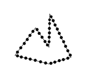
With fixed pitch laser control (FPLC), the laser is triggered to fire an optical pulse at fixed increments along the laser path regardless of varying speeds. In the geometry example (Fig. 7), laser spots are placed along the path at constant increments even as the motion speeds up along the straightaways and slows down at the corners. The density and rate at which laser pulses are triggered are settable parameters, and can be changed on the fly. In fixed pitch mode, the pulse placements are independent of the path points.
Pulse-On-Demand Control
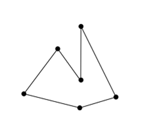
With pulse-on-demand control (PODC), laser pulses may be placed at arbitrary, exact locations on any geometry. In PODC mode, the location of the pulse placement needs to align with path points. If exact placement of laser pulses is required then position-velocity-time (PVT) path planning is recommended. If placement of pulses can be specified within a small tolerance, then linear and circular interpolation path planning can be used.
About Polaris Motion
Polaris Motion specializes in motion control solutions for CNC machines in laser-based manufacturing, diamond tool cutting and grinding of optical surfaces and for specialized CNC machines in other high performance areas.
Information on multiple Galvo scanner control and our 32 page general catalog (5MB) may be downloaded here.
Polaris website.
Mile Erlic
Polaris Motion
www.pmdi.com
merlic@pmdi.com

