The Fastest Constant Speed Can Make a Huge Difference for Advanced Manufacturing
In today’s competitive manufacturing landscape, producing components on a large scale—from thousands to millions of parts—is fundamental to industrial operations. Efficient manufacturing is crucial for economic viability and optimized throughput.
To achieve this, many facilities increasingly rely on advanced automated machinery that dynamically adjusts speeds along the tool path. This capability lets machines accelerate on straight sections and decelerate at corners, optimizing production time.
Variable speed motion is suitable for applications where precision is less critical, such as rough cutting with CNC machines where the exact surface finish is not a priority, or pick-and-place operations that require speed over precision.
However, many manufacturing processes rely heavily on constant-speed toolpath execution to meet specific quality metrics. Some of these include (1) consistent epoxy dispensing (2) better fusion in seam welding, (3) uniformity of laser energy deposition for glass scoring.
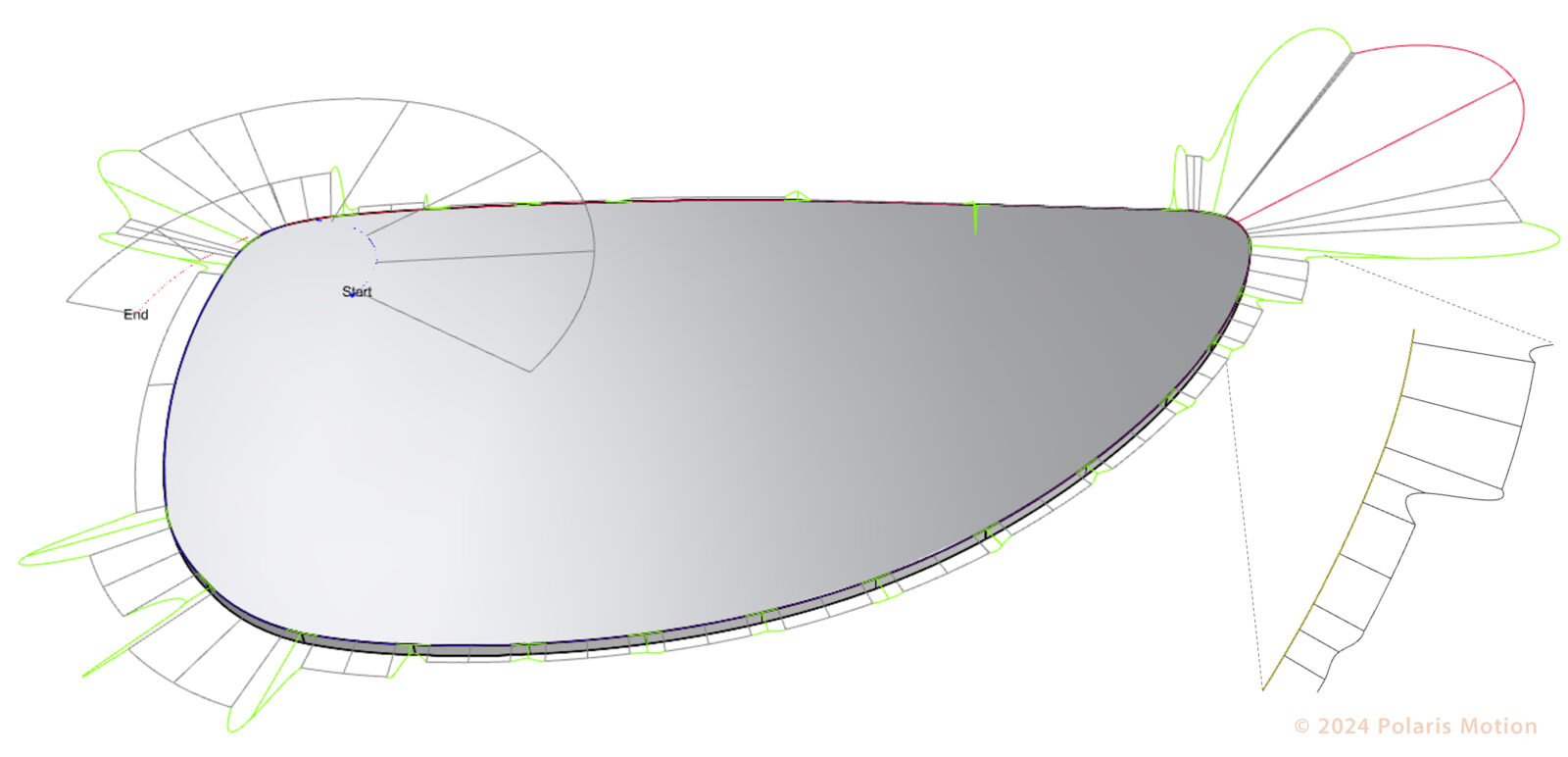
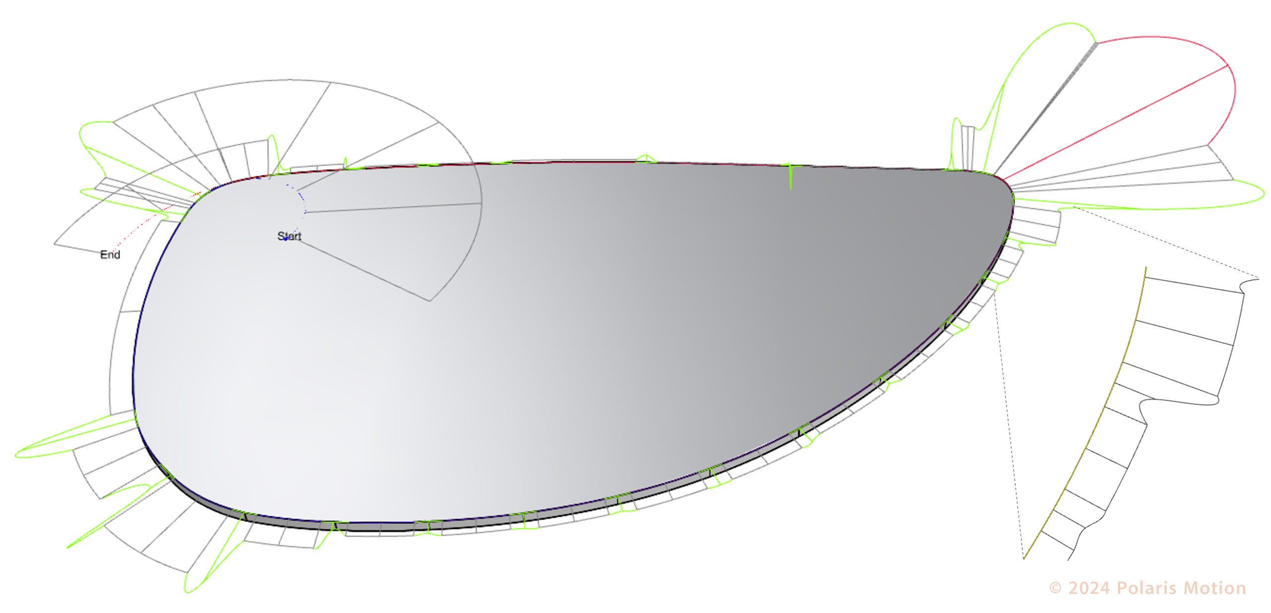
Figure 1: The Eyeglass part in PolarisCAM 2D shows a curvature graph with transition curves between drawing primitives.
Other constant-speed manufacturing processes significantly benefit surface finish and form accuracy including high-precision metal milling, grinding, waterjet cutting, and single-point diamond turning.
Skilled applied scientists and developers have responded by developing new techniques and algorithms to optimize throughput in constant-speed operations, providing cutting-edge performance. These advancements allow easy integration and adaptation.
By adopting this technological innovation, manufacturers can significantly enhance their production capabilities, meeting current demands and preparing for future manufacturing challenges.
The integrated workflow provided by the new, optimized constant-speed process is easy to use:
- Input the CAD drawing
- Input the contour displacement tolerance
- Configure the kinematic ability of the CNC machine tool
- Output the constant-velocity-ready G-code file
- Execute the G-code file on the CNC motion controller
This new constant speed process provides important advantages, for example:
- Fastest constant feed rate
- Least constant feed rate variation
- Better surface finish
- Easy creation of G-code part files
- Guaranteed part completion
Performance for Constant-Speed Laser-Scoring of an Eyeglass Part
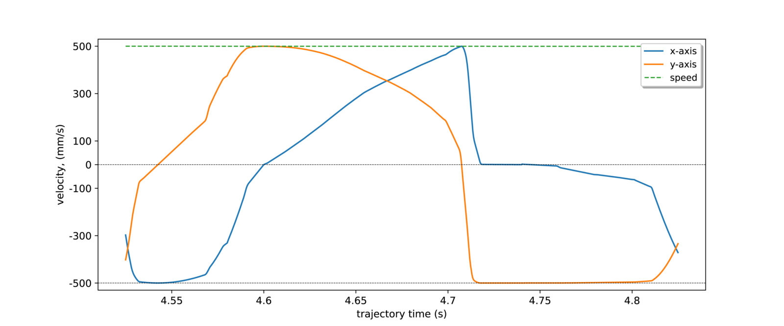
Figure 2: The x-axis, y-axis and the net constant commanded velocity generated from PolarisCAM 2D.
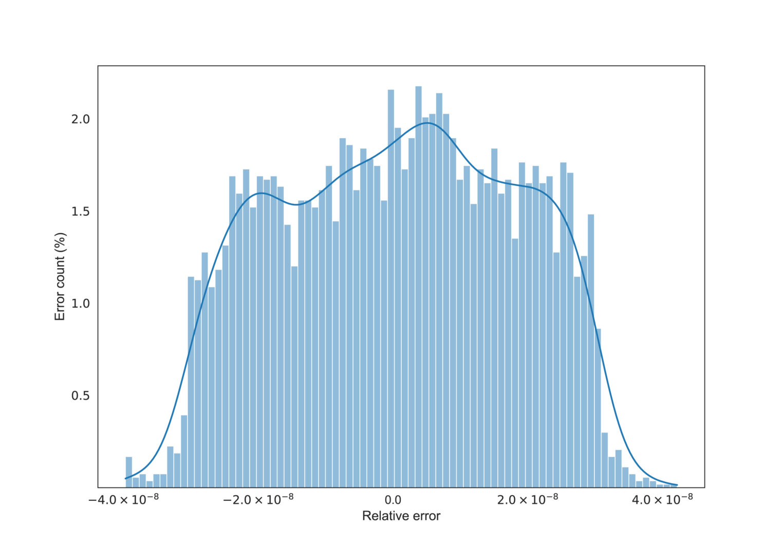
Figure 3: Histogram illustrating the deviation between setpoint and desired constant velocity of 500 mm/s.
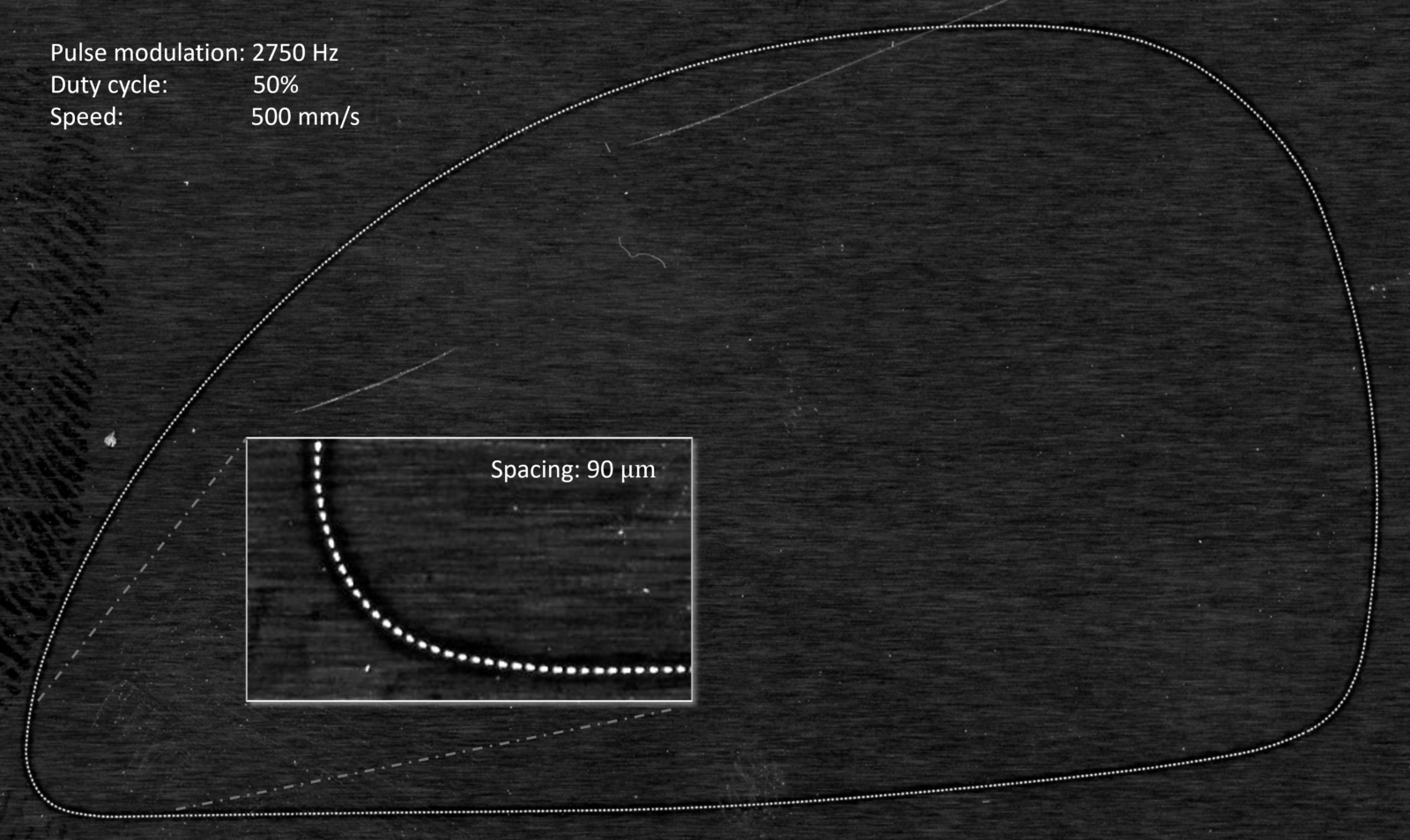
Figure 4: Constant speed trajectory marked at 500 mm/s with PRR 2750 Hz and 50 % duty cycle at 20 kHz setpoints.

