An Easy-to-use, Integrated Laser Based Motion Control Solution for Machine OEMs
When a precision machine designer is planning a new project, they must consider the performance, the cost to produce and maintain the system and the ease of use. A user-friendly motion control system has the benefit of reducing development costs and minimizing time to market. With this in mind, we designed the Polaris Motion Control system to ensure an easy installation, without sacrificing configurability and high performance.
We’ve created an ecosystem of powerful hardware, and feature rich software. This ecosystem allows you to integrate your favorite servomotors, encoders and other peripherals into a final machine tool product with smart motion control features. Beyond easy machine configuration, advanced machining operations are easy to implement using Polaris CAD/CAM.
Setting Up and Using a Polaris Motion Control System
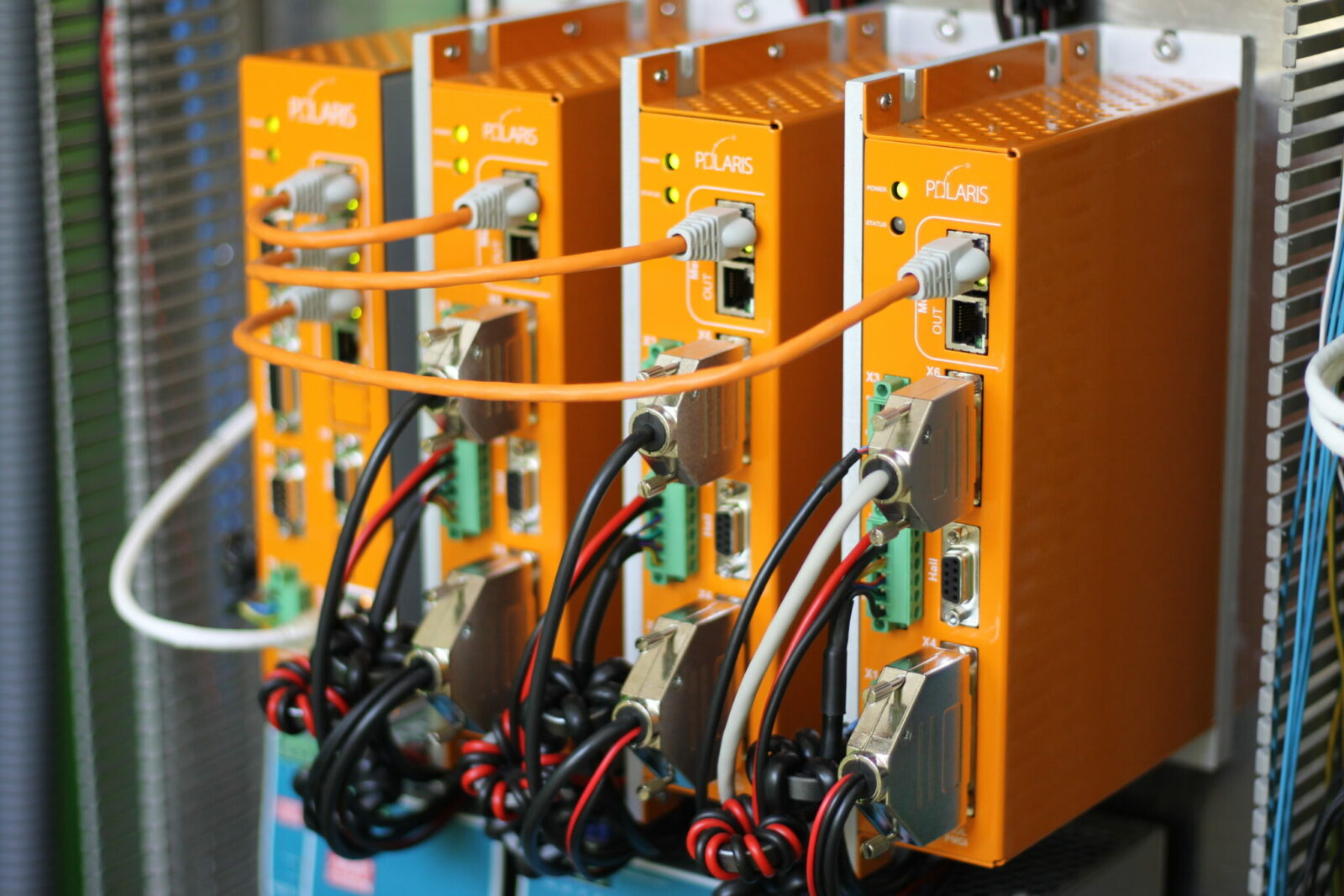
Wiring Your Polaris UniverseOne™ Control System
Configuring the Mercury™ network is an easy task. Due to auto-enumeration and auto-configuration, the devices are automatically identified and configured on startup.
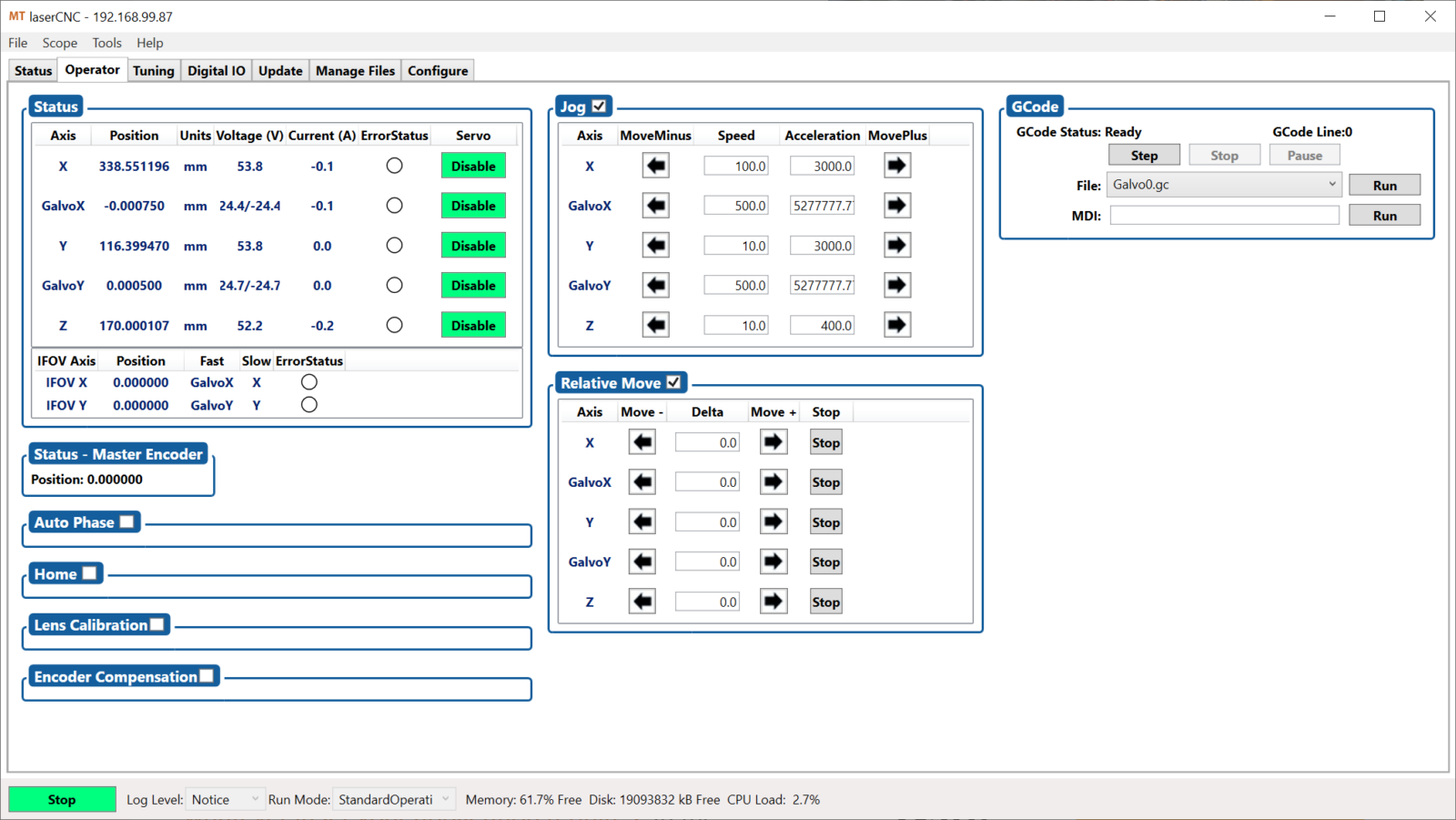
Simple Configuration and Tuning Using MotionTools
After the network and electrical is wired, you will move to MotionTools, our desktop application that allows you to interface with your Polaris Controller, drives and other devices on the network. In MotionTools you will find powerful graphical tuning utilities, a fully featured real-time scope and user-friendly wizards that allow you to integrate lasers into your multi-axis machine.
MotionTools is organized in a very logical manner and the server programming is easy to understand for a software developer.
Luis Garcia
Software Engineering Team Lead
Mundt & Associates, Inc.
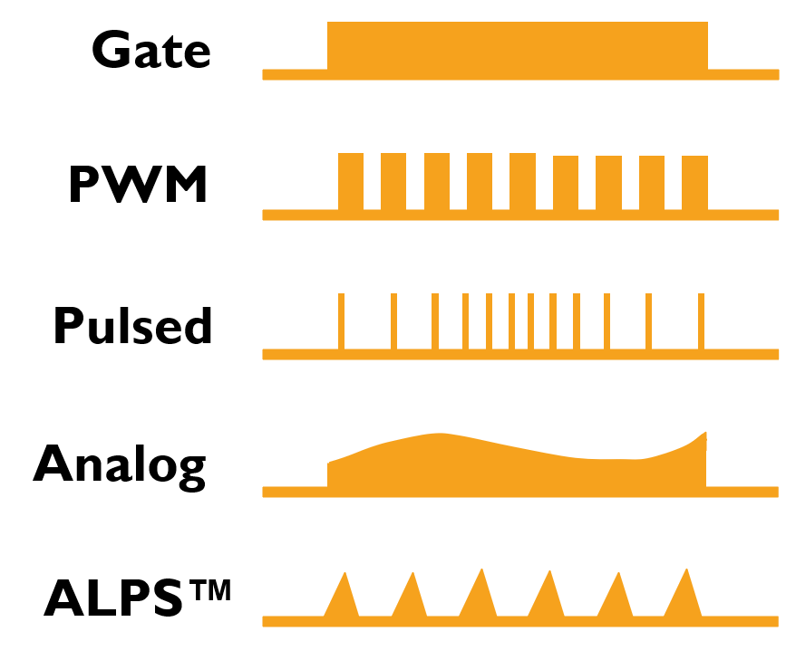
Exploring our Advanced Laser Triggering Toolkit
Over years of listening to our customers and taking their feedback seriously, we’ve created an extensive toolkit for controlling any laser your application needs. In the Polaris Motion triggering toolkit, there are five main modes of laser triggering (Figure 3). We have options for both Pulsed and Continuous Wave (CW) lasers, including our proprietary Arbitrary Laser Pulse Shaping (ALPS™) mode. Should you have an application that requires two or more laser sources in a single operation, our toolkit supports multi-laser triggering. All of these modes are easily implemented and customized. In addition, several automatic laser control features are available. These include auto-frequency and auto-duty cycle PWM triggering modes that make sensitive operations like welding, repeatable and of high quality, every time with no guess work.
Substitute Skywriting with Fixed Pitch Triggering to Accelerate Part Processing Time
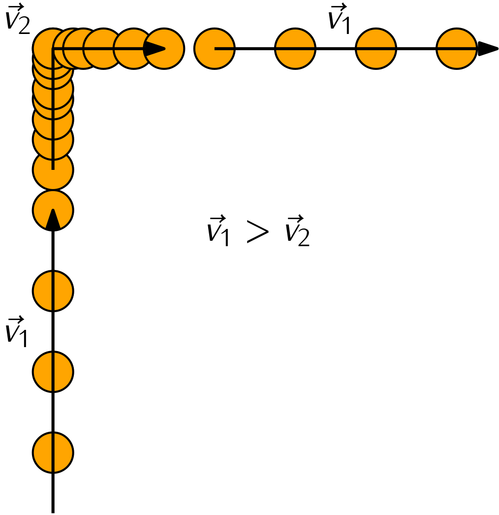
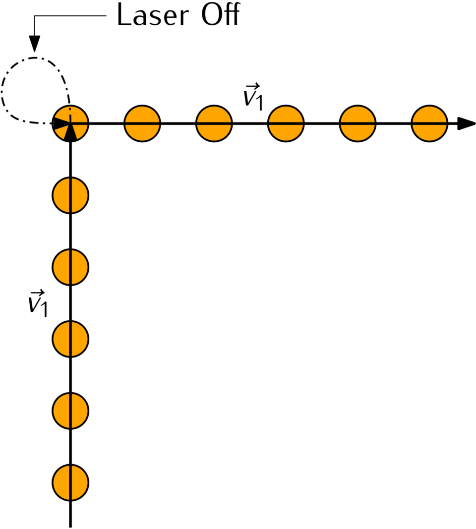
In laser-based material processing, the energy delivered to the workpiece per unit area (fluence) is of primary importance. The ideal scenario is to keep the fluence constant at all points along the planned trajectory. If you are using a fixed laser pulse rate, and the machine needs to slow down for a corner, over-burning (an increase in fluence) results (Figure 4). This problem is often remedied by implementing a motion-based solution, often called “skywriting”. When skywriting is enabled, a constant velocity is maintained at corners, resulting in consistent fluence from the fixed laser pulse rate. Skywriting achieves this result by adding an extra movement at corners, where the laser is precisely turned off, motion is looped, and the laser is turned back on once the machine has reached the requisite marking position and velocity (Figure 5).
A Superior Solution
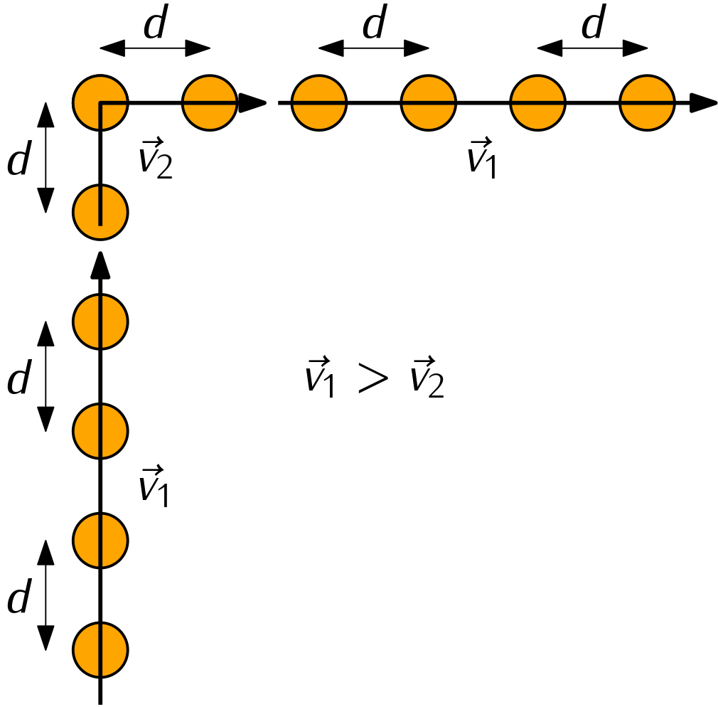
While skywriting achieves constant fluence, it adds significant processing time, which is undesirable in production. Polaris Motion has developed an improved solution for laser power delivery that is independent of velocity, acceleration and jerk. Our fixed pitch laser triggering hardware algorithm fires the laser based on the distance that has been traveled along the planned marking path (Figure 6). Our spacing based approach allows for maximum processing speeds at corners; it creates no wasted movements; and most importantly, it delivers steady fluence for superior and consistent material processing.
Setting up pulsed lasers was incredibly easy with Polaris, and the fixed pitch triggering was genuinely one of the coolest features that I have used. It provided consistent surface marking while removing speed and frequency as variables in laser power delivery.
Andrew Hargreave
Automation Engineer
DynaVap, LLC
No Need to Rewire your System When Changing Laser Triggering Modes
You may be accustomed to changing peripheral wiring when an alternate triggering mode is required for a project. This is not the case with Polaris Motion. We have created an alternate, more flexible laser control method. Simply route a digital output from the Polaris control system to your laser of choice. This output sends the necessary information to trigger your laser according to our laser triggering hardware algorithm. There is no need for complicated encoder re-wiring and splicing. The laser triggering mode is easily changed in Polaris CAD/CAM via a dropdown menu.
Using Polaris CAD/CAM Makes Toolpath Generation and Machine Operation Easy
Create an all-in-one solution when you pair a Polaris Motion Control system with Polaris CAD/CAM. This software allows you to import CAD drawings, set marking parameters, and generate G-code toolpaths rapidly and with ease. The toolpath output is sent automatically from CAD/CAM to your Polaris Controller for execution. Polaris CAD/CAM has advanced machine vision capabilities, allowing you to set up efficient and robust lens calibration recipes. You can even compute projections onto 3D objects (Figure 7) for applications such as engraving on cylindrical objects. Whatever your application, CAD/CAM is built to make toolpath generation simple and fast.
Your Polaris Controller Automatically Interprets G-code
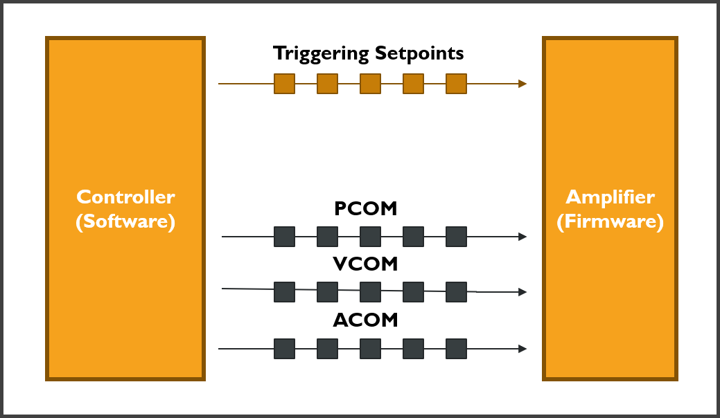
Once your servo axes and laser source are configured, and you have a G-code file ready to run, the Polaris Controller does the rest of the work. The Polaris Controller interprets the G-code, converts the movement commands to dynamic setpoints, and sends synchronized laser triggering setpoints automatically (Figure 8). Our system supports virtually any linear or rotary servomotor, stepper motors and can send commands to standard Galvoscanner interface protocols like SL2-100, HSSI and XY2-100.
Polaris Infinite Field of View (IFOV)
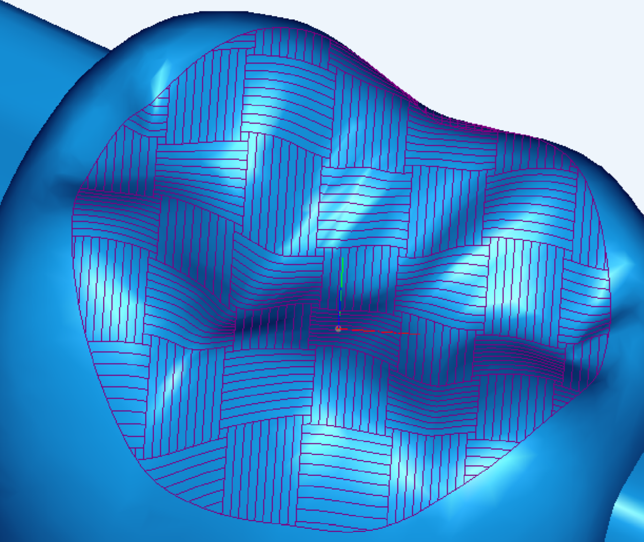
When using a Galvoscanner for laser material processing, the field of view (FOV) is the limiting factor determining the maximum part size that can be accommodated. This draw back is often circumvented by integrating a scan head onto a Cartesian stage, making larger parts possible (Figure 9). The traditional method of combining fast Galvo motors with slower, long stroke stage actuators is by using tiling (Figure 10).
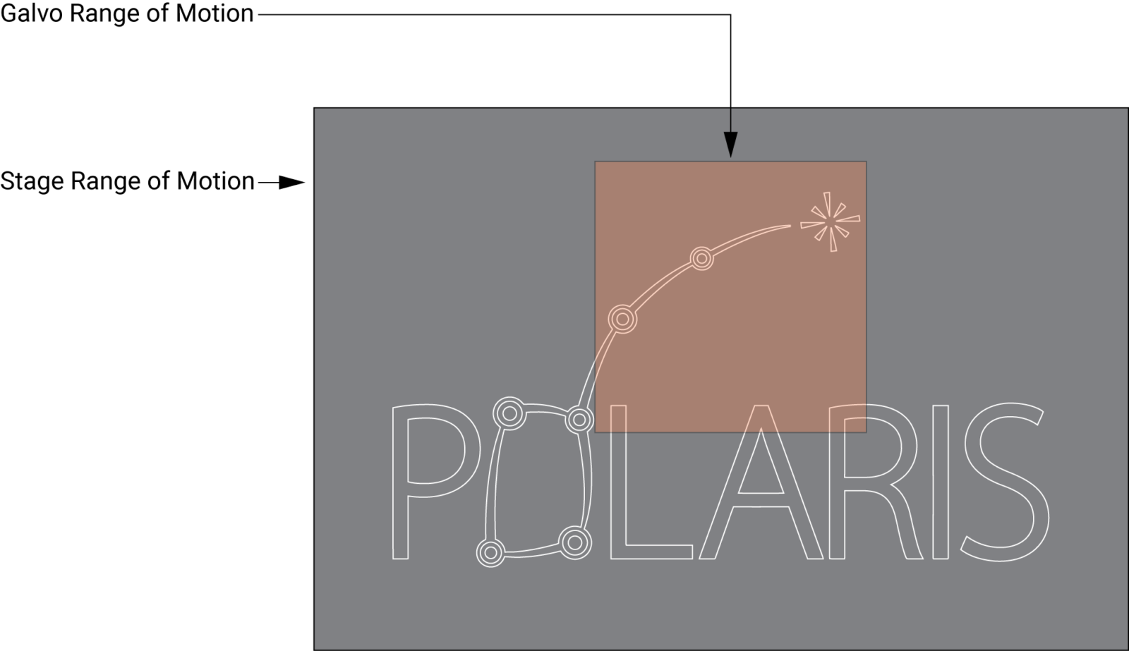
IFOV is an improved solution over tiling. IFOV is a technique used for laser material processing where a Galvoscanner is moved over a large marking area in a smooth and continuous fashion using the stage (Figure 11). This technique remedies the common issue of stitching errors that occur when using tiling. Stitching errors are inconsistencies in the laser path that appear along the seams of the tiled sections (Figure 12). Combining the advantages of a Galvoscanner and stage using IFOV technology makes it possible to laser machine large parts with great detail at high speeds.
Polaris IFOV is fully configured using just seven settings. Four settings define the axes. Of the remaining settings, one toggles IFOV on/off, and the remaining two define the weighting of motion distribution between the stage and the Galvoscanner.
Polaris Motion’s background is in CNC machine tool control. As such, our IFOV technique is fully compatible with standard G-code files. This includes linear interpolation (G1), circular interpolation (G2/G3), spline interpolation (G5), work coordinate transforms, tool offsets and more. Galvoscanner and stage motions can be linked and un-linked.
We support third party Galvoscanners with standard XY2-100, SL2-100 and HSSI interface protocols. Simply select the Galvoscanner that makes sense for your application. There is no need to swap out your servomotors or drives either since we support most third-party vendors. Simply connect our motion control system to your existing drives and Galvoscanner and get IFOV going right away.
If you are a machine tool OEM looking for a robust and easy to use motion control system, drop us a line to set up a demo!
About Polaris Motion
Polaris Motion specializes in motion control solutions for CNC machines in laser-based manufacturing, diamond tool cutting and grinding of optical surfaces and for specialized CNC machines in other high-performance areas.
Tom Erlic
Polaris Motion
www.pmdi.com
terlic@pmdi.com